In this video, we will work on a electric brushless motor. However, there is no datasheet for this motor. We got this torque motor for our lab for cheap. An Internet search did not bring up any useful references. As such, this motor is an ideal testbed that would help us illustrate key principles of how Servosila brushless motor controllers are configured.
This motor has just three wires. This means it is a sensorless motor. If the motor had Hall sensors, it would have had additional signal wires. The motor features a lot of coils. This means it is designed for torque, rather than for speed.
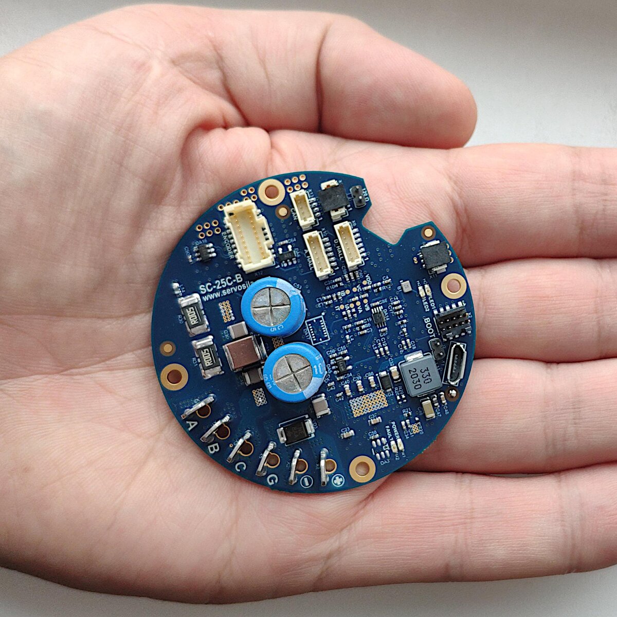
Servosila brushless motor controllers come in circular or rectangular shapes. The servocontrollers are designed for robotic applications including Direct Drive control and servo motor control. The controllers has built-in sensing capabilities that we will utilize to run this no name torque motor.
I connected three phases of the motor to one of my Servosila brushless motor controllers. Since I do not know which phase is A, B, or C, I connected the wires arbitrarily. I powered my controller from a desktop power supply unit. I used a regular USB cable to connect the controller to my computer. The other option is CAN bus, but for this video we will use USB.
Now lets power up the motor controller. The light on the controller tells the power is on. Rotating the motor becomes a bit harder, since it now acts as power generator and pushes electric current through the controller.
Now lets launch the Servoscope software tool that accompanies the controllers. Refer to our previous videos for instructions on how to install it on Windows, Linux or Raspberry PI computers.
Servosila brushless motor controllers come with a powerful auto-configuration capability that automatically measures various vital characteristics of the motor, and greatly simplifies commissioning of new motors. To launch the auto-configuration routine, first, I need to figure out what maximum phase to phase current my motor can handle, and how many rotor poles the motor has.
Just for completeness, let me show you how one could configure the controller without using the auto-configuration function. There is a tool called Spreadsheet. Here you fill out a form with various datasheet parameters of your motor such as resistance, inductance of the phases, Back-EMF constant, and so on. The tool computes various control law parameters displayed on a separate tab. Here, you can tweak dynamics and performance characteristics of your drive by moving the sliders. Then you press the Save button, and the controller gets configured for your motor.
Since I do not have a datasheet for my motor, I will use Auto-Configuration routine. This means I need to figure out how many rotor poles my motor has.
Counting stator poles is easy. You just count the coils. But that's not what we need. We need rotor poles. The problem is that the motor's permanent magnets are hidden inside this outrunner rotor, and we just cannot access the magnets to count them.
So, here is a trick of how you could count the rotor poles. There is a command called Direct Field Control: Rotation. Specify a very small voltage that will surely not burn the motor, for example, 0.3 Volts. Then, specify the speed of exactly 1 Hertz. Hit the Send button.
If everything is connected properly, the motor should start rotating slowly. We need to measure time it takes for the rotor to make a complete turn. By the way, congratulations! The motor is alive and is connected properly.
To measure the time it takes the rotor to make a full revolution, I use a simple stop watch setup. The battery is just a random object that designates the start and the finish point. I simultaneously start the clock and send the Direct Field Control command to the controller. The controller starts rotating magnetic field of the stator with specified speed of 1 electrical Herz, or revolution per second. The rotor is following the magnetic field of the stator, just like a donkey follows a carrot. But, we can quickly notice that the rotor is rotating much slower than specified 1 revolution per second. How much slower is what will give us the answer on how many rotor poles the motor has. The more rotor poles the motor has, the slower the rotor moves when the controller rotates the magnetic field of the stator.
It took the rotor 21 seconds to make a full revolution. Double that, and you will get the number of rotor poles. Our motor has 42 poles. This is an unusually high number of poles. Typically, you would see anywhere between 8 and 14 poles. That our motor has 42 poles, tells us that its designers wanted to increase torque at expense of speed. Increasing the number of rotor poles is somewhat similar to adding a speed reducer to the motor.
Now that we have determined the number of poles, we can specify it as an input parameter into the auto-configuration command. Which brings us to the next question. How much phase-to-phase electric current can this motor handle? Typically, you would get this data from the motor's datasheet. However, we do not have a datasheet for this motor.
Let's think of significance of the maximum phase-to-phase current's limit. Torque of the motor is proportional to the current. If we set the limit for the current too low, then the motor will not produce its maximum torque. If we set the limit too high, then the motor will not be able to dissipate all the heat that the current produces, and might get fatally damaged by the heat. Unfortunately, there is no good way to experimentally tell the exact limit, since we would have to burn a few motors to find the current that starts damaging the motor. It is better be on the conservative side, and initially set the limit lower. I searched the Internet for similar motors, and determined that most likely my motor can handle between 20 and 30 Amps max. I am going to set the limit much lower, at 5 Amps. I will raise the limit later to get the maximum torque out of my motor.
Pressing the Send button starts the Auto-configuration procedure. The motor accelerates to its maximum speed during the procedure, so I have to keep it in place by hands. Otherwise, it might just fly off the desk. As expected, the motor produces beep sounds at the beginning and at the end of the auto-configuration routine.
We can now inspect the results of the auto-configuration procedure. The controller automatically filled out the Datasheet section of the configuration tab. The current limit and the number of poles is what we specified when launching the routine. The phase resistance and inductance as well as Back-EMF constant and the rotor's moment of inertia have been measured automatically during the procedure. Notice, the the controller did not detect Hall sensors since we did not connect any.
Lets do some basic sanity checks. There is a useful bit of information printed on the motor. The KV constant has a known relation to Back-EMF constant that the controller automatically measured during the auto-configuration routine. You can convert KV constant to Back-EMF constant, and vice versa. So, lets convert the measured Back-EMF constant to KV, and compare the result to what is printed on the motor. This way we can make sure that the auto-configuration results can be trusted.
I load the measured value of Back-EMF constant into a conversion tool. The tool needs to know the number of poles in order to work properly. The tool tells that the KV constant of the motor is 154. This is fairly close to KV 135 printed on the motor. I would say the auto-configuration results make sense. You would normally compare the measured values of resistance, inductance and moment of inertia to datasheet values, but in our case, we just have to trust our instruments.
Lets run the motor. I choose Electronic Speed Control command from the list, and specify 100 electrical Hertz as the target speed. The motor starts spinning.
There is a special testing command that helps verify controllability of the motor at different speeds. The command gives a sinusoidal speed reference to the controller. In other words, the motor accelerates in forward direction, then accelerates in reverse direction, then repeats the cycle. The speed changes from positive to negative according to a sine law.
Use this command and other similar commands from the same list to test your electric drive.
I hope you've found this video useful for your project. Please subscribe to our YouTube, Telegram and Twitter channels. Thank you for watching.