#raspberry #raspberrypi #raspberry pi 4 #raspberry pi #bldc #pmsm
In this video, we will control a pair of brushless motors using a Raspberry PI computer. We will use one of the computer's USB ports to connect a network of brushless motor controllers.
Servosila brushless motor controllers come in rectangular or circular form factors. The motor controllers feature USB and CAN ports for connecting to control computers such as Raspberry PI.
We will power the computer, the controllers, and the brushless motors using a single battery, similar to a autonomous vehicle design. The controllers need 7 to 60 Volts DC. The first motor is an outrunner type, a kind of what you would use for a vehicle propulsion. The bigger motor comes with a quadrature encoder which means it can be used as a powerful servo.
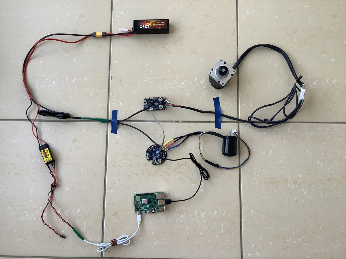
I made a cable to power my set up. On one end, the cable has a socket for plugging the battery. The cable splits into a two parallel parts to power the controllers, and the Raspberry PI. One part of the cable further splits to power a pair of brushless motor controllers. I put proper connectors at the ends of the cable, so that I could just plug it into the controllers. I am using an 11.1 Volts RC battery that I got in a local hobby store.
This should look like an autonomous vehicle to an eye of an electrical engineer. The setup has an autonomous source of power, a WIFI-based radio link, an on-board computer, and a set of actuators.
The upper part of the cable goes into a SBEC module that I got in the same hobby store. The SBEC module converts whatever voltage the battery provides, into a regulated 5 Volts DC voltage that Raspberry PI wants. I extended my setup with a USB cable. This way I provide a 5 Volts DC power from BEC to my Raspberry PI via a USB connector that the computer needs.
Now, lets plug the motors into the controllers. Although the motors have Hall sensors, I will only plug the motor's phase wires for this video. The controllers will treat the motors as sensorless ones. I suggest that you watch separate videos dedicated to Sensored, Direct Drive or Servo Control modes of operation.
A regular USB cable is used to connect the Servosila brushless motor controllers to the computer. Only one of the controllers in the network needs to be connected to the computer.
Next, we need to build an internal CAN network between the brushless motor controllers. We are going to use a CANbus cable to interconnect the controllers. Each controller comes with two identical CAN ports that help chain multiple controllers together in a network. Up to 16 controllers can be connected this way via a single USB cable to the same control computer or a PLC.
If one of the interconnected brushless motor controllers with CAN bus is connected to a computer via USB, then that particular controller becomes a USB-to-CAN gateway for the rest of the network.
Once you plug the power supply cables into the motor controllers, and into the Raspberry PI computer, you will see the following cabling network. I spread it out on the floor to make it easier to trace. Be very careful with voltage polarity when connecting the motor controllers to a power supply.
We need to install a software tool called Servoscope on the Raspberry PI computer. Download the Servoscope package to your Windows or Linux computer. Launch VNC client software and connect to the Raspberry PI computer.
Now that the package has been uploaded to Raspberry PI, we need to un-zip it, and launch the Servoscope application.
Open the Terminal and navigate to the directory with un-zipped file. Launch the Servoscope application by launching a script:
./servosila.sh
To connect to the motor controllers, pick a proper serial port from the drop-down menu, and click the Connect button.
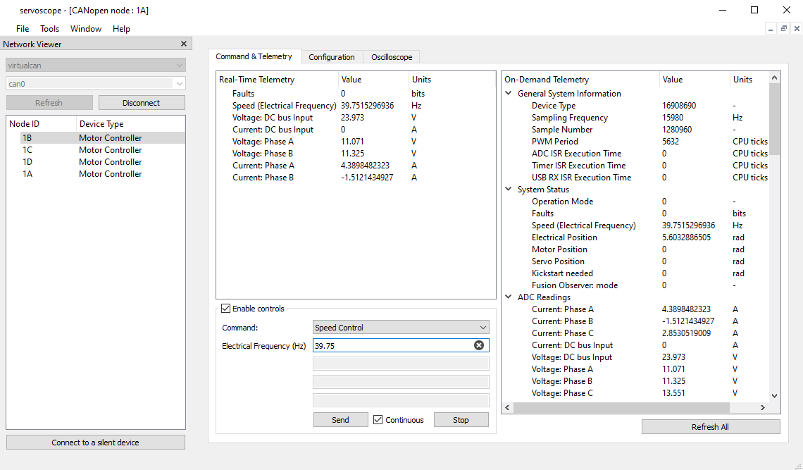
Both controllers in our network appear in the list of devices. Double-click on a device name to open a command and configuration window. You may wish to close the Network Viewer and Help Viewer windows to free up screen space for monitoring multiple controllers at the same time.
Please note that the motor controller appears to Raspberry PI OS as a virtual serial port. Any application running on Raspberry can read and write to the serial port.
There is a way to find the virtual serial port in the Terminal by listing all serial devices:
ls -la /dev/tty*
The motor controllers send telemetry via the virtual serial port. Use the following Terminal command to display telemetry. The motor controller uses a text protocol to send telemetry. Your applications can send commands back to the controller by writing the same kind of text strings back to the serial port. The other option is by using CANbus. We will look at CANbus interface in a dedicated video.
We need to initiate an Auto-Configuration routine for both of our motor controllers. From the drop-down menu, pick the Auto-Configuration command. Specify a maximum phase-to-phase electric current that your motor can handle. Specify the number of poles your motor has. These values normally come from the motor's datasheet. Click the Send button.
The motor starts making what looks like mysterious moves during the auto-configuration routine. What happens is that the controller sends sounding electrical signals to the motor. This way the controller measures various characteristics of the motor, and then configures itself for this particular motor. The probing signals cause the motor to make the kong-fu moves.
The motor accelerates to its maximum speed. Be careful as the motor is producing its maximum torque at this moment. The rapid accelerations may take place a few times during the auto-configuration procedure.
The beauty of the Auto-Configuration function is that the controller automatically configures itself when commissioning a new motor. I suggest that you watch a separate video dedicated to peculiarities of the Auto-Configuration routine. Now that the controller of the out-runner motor is configured, we need to repeat the procedure for the second motor.
Now the second motor starts making the auto-configuration moves. The auto-configuration routine takes several seconds. The duration depends on the responses the controller receives from the motor.
As both motors have been commissioned, we can start sending commands to the motors. For example, lets issue an Electronic Speed Control command to the bigger motor. Pick the command from the drop-down menu. I specified the speed of 100 electrical revolutions per second. The motor starts spinning with the commanded speed
The way the Electronic Speed Control works is that the controller automatically increases or decreases torque to maintain a constant commanded speed. We will look at Servo Control, Direct Drive Control, and other modes of operation in subsequent videos.
The green LED light tells that the controller is receiving commands from a parent control system.
Now it is time to develop your control logic. By the way, if you want to know how a motor command looks like, the one you can send to the controller via the virtual serial port or CAN, you may click the View button.
In this video we looked at how to connect brushless motor controllers to a Raspberry PI computer powered by a battery. We will look at CAN interface option in a separate video.
SERVOSILA SC-25 Brushless Motor Controllers are miniature electronic units that provide high-precision control over a wide range of mechanisms actuated by brushless electric motors (PMSM, BLDC) of any manufacturer. The controllers turn brushless motors into computer-controlled traction drives, high-precision direct drives, or servo drives when (optionally) paired with absolute position encoders (BISS-C, SSI, SPI, PWM or Quadrature) of any manufacturer.
Up to 25A of phase-to-phase current, and up to 20bits of angular precision are provided. The electronic units feature a microprocessor chip, a set of absolute encoder interfaces for shaft position measurements, a firmware implementation of advanced motion control algorithms that operate in a closed loop fashion, as well as CANbus/CANopen and USB 2.0 interfaces for receiving commands from a control computer/PLC and sending back telemetry.
The brushless motor controllers are extensively used in various products of Servosila including its lines of robotic arms, and servo drives. The controllers’ design incorporate multiple lessons learned by Servosila while operating its robots in various environments.
Make sure you subscribe to our YouTube and Telegram channels.
Ask questions on live chat on Telegram.