Today we will review a product called Led Amplifier. We need it in those cases when we connect several tapes into one long one. If we do not use amplifiers, the color at the beginning and at the end will be different. This happens because the tape has its own small resistance and the voltage on each subsequent meter of the tape is lower than on the previous one. For those who do not know what this problem is, you will find a photo of the same tape at the beginning and at the end below.

This is a translation of my article in Zen. Also, do not forget to read us in other services: Instagram, telegram (RU, EN, DE). Medium, LiveJournal, YouTube.
Above you can see the same difference in color on the same tape. There are many ways to solve this problem. RGB amplifiers are one of them. The device under review could not solve my problem (RU). In this article (RU), I wrote about a simple controller with Ali. I think that everything works with it without problems, but I did not check it. I connected this amplifier to a Xiaomi controller. Below, in the photo, the oscillogram before and after the amplifier.
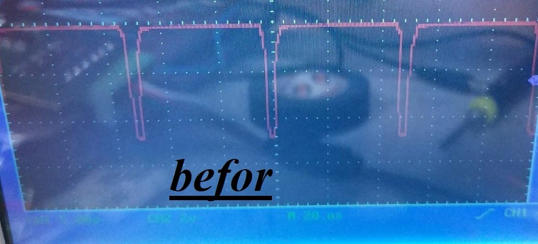
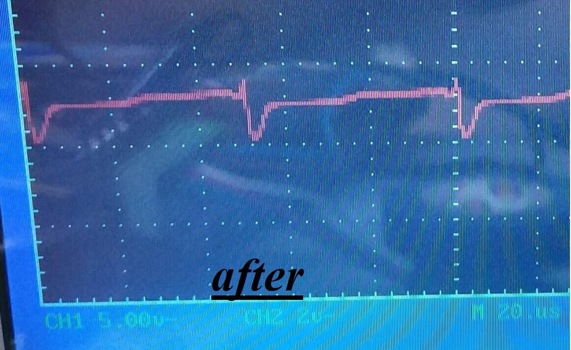
I assume that this is due to the high speed of the PWM generator of the RGB controller. The amplifier simply does not have time to repeat the input signal. Therefore, the color of the diodes before and after the amplifier differs very much, and in some modes, it does not work at all. I bought a few ~40pcs of such controllers. And now I'm thinking what to do with them. Let's analyze one:
Here is a product in a heat shrink with two power wires and connectors "input" and "output". We remove the heat shrink and look at the contents in detail.
I drew an example diagram below. There may be errors here, please let us know if you find them.
On the board we have a 4-channel comparator lm324, a 4.7 V voltage source (made on 2 resistors and a zener diode) and 3 transistors (something like A2sHB). As we remember, the channels on the led strip have a one plus and are controlled by a minus. The input for each channel is connected through a 1:10 resistive divider to the inverse input of the comparators. The voltage at the inverse input will be +12V and drops to 1.2 V at the time of the diode it glows. And the voltage from 4.7V voltage source is connect to the positive input.
The circuit works as follows: when a signal from the controller arrive to the input, the voltage at the positive input is more than voltage at the inverse input and the comparators output open the transistor, giving a minus to the led amplifier output. Otherwise, the voltage at the inverse input more than the level at the direct input (positive input) and the transistor is discharged and closed. The scheme is good, but work slowly. If you look at the gate of the field-effect transistor, then in my case the transistor is not in the PWM-mode and work in a linear-mode. The transistor just doesn't have time to charge and discharge gate. When we try to set a low brightness, around 10%, the transistor does not open. Therefore, this scheme isn't applicable to work with xiaomi controllers, which work ~18 times faster than low-cost RGB controllers. I think that if I loaded such amplifiers, the transistors would immediately give their white soul to the air.
And that's all, subscribe, likes, repost... And we will soon be a small lottery ☺.